2/B, Firdous Masjid Market, Mirpur 2, Dhaka 1216
+88-01633442266
Saturday-Friday: 09:00 AM - 06:00 PM

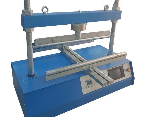
Flexural Device on Concrete Beam

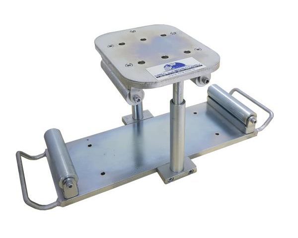
Flexural device for two points and center point tests on concrete beams is complete with two lower rollers, one of them articulated, and two upper rollers for third point tests.

• Two fix distances between lower rollers: 300 and 450 mm

• Two fix distances between upper rollers: 100 and 150 mm

It is possible to place in the center only one upper roller for center point tests.

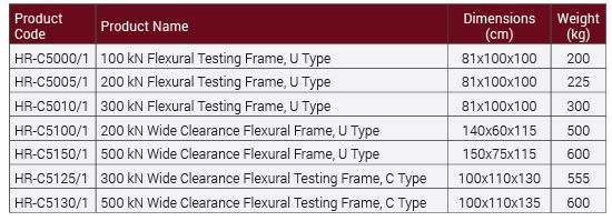
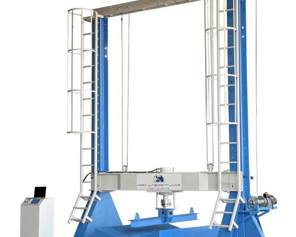
Flexural Testing Frame

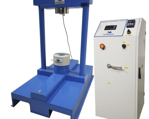
The multipurpose Flexural Testing Frames are designed for minimum deflection at maximum load resulting in very high accuracy. The load frame is a welded steel fabrication carrying the ram fitted to the steel base. All Frames have a single acting up stroking ram with over travel switch protection to stop the machine when maximum ram travel is reached. A load cell is used for load measurements on all frames.

Flexural Frames are designed to accept all accessories required for flexural or compression tests.

Flexural Frames are100 kN, 200 kN, 300 kNcapacity U Type and 300 kN, 400 kNcapacity C Type open structure designed to allow easy and practical front loading of the specimen.

The very rigid C type design is ideal either for conventional flexural test or for more sophisticated tests such as deformability and ductility index.

The load frame provides the stability needed for accurate and repeatable test results over the years of operation.

Flexural test assemblies should be ordered separately.

All frames can be connected to compression machine as a second frame or can be used with any power pack as an independent Flexural Machine.

The main characteristics are:

• High stability welded assembly
• High accuracy load measurement with load cells
• Can accept wide range of accessories for mentioned standards
• Can be connected to Compression Machine or Hydraulic Power Pack

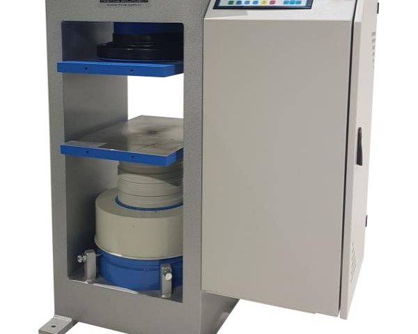
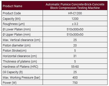
Automatic Pumice Concrete-Brick-Concrete Block Compression Testing Machine

The Automatic range of 1200 kN capacity compression testing machine has been designed for reliable and consistent testing of a Pumice Concrete, Brick and Concrete Blocks of specimens.

The dimensions of the upper and lower plates allow the testing of sample on 510x310x50 mm compression plates, concrete blocks and building materials.

Tests can be performed by controlling the machine either H-Touch Pro Max Control Unit or on a computer with using free TEST Software which is provided free of charge with the machines. There are several advantages of performing tests on computer with using TEST Software, such as reporting and graphical output.

The Automatic Pumice Concrete-Brick-Concrete Block Compression Testing Machines allow inexperienced operators to perform the tests. Once the machine has been switched on and the specimen is positioned and centered by the help of centering apparatus. The only required operations are;

  • Setting test parameters, including pace rate (only required when the specimen type is changed).
  • Pressing the START button on the control unit
  • The machine automatically starts the rapid approach, when the specimen touches the upper platen the rapid approach is ended and starts loading at the pace rate that selected by user and stops once the specimen fails.
  • Automatically saves the test parameters and test results.

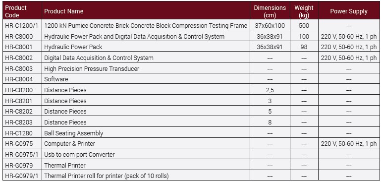
The Automatic Pumice Concrete-Brick-Concrete Block Compression Testing Machine consist of;

Load Frame,
Automatic Hydraulic Power Pack,
Digital data acquisition & control system,
Distance Pieces, 30 mm and 50 mm,
Upper Platen (with ball seating assembly) 510x310x50 mm,
Lower Platen 510x310x50 mm,
Loading Cylinder Assembly & Limit Switch for safety,
Software and Ethernet Cable.

Pumice Concrete-Brick-Concrete Block Compression Load Frame

The Load Frame is made of welded steel walls the piston is placed in the center of frame.

The load frame provides the stability needed for accurate and repeatable test results over the years of operation.

Upper Platens/Lower Platens

Upper Platen (with ball seating assembly) 510x310x50 mm and Lower Platen 510x310x50 mm.

• Manufactured from high quality steel, which is then hardened, smoothed and finished.
• The roughness value for the surface texture of the auxiliary platens is ≤ 3.2 µm.

Distance Pieces

Distance pieces are used to reduce the amount of vertical clearance between the upper platen and the lower platen. Supplied with 30 mm and 50 mm distance pieces.

Loading Cylinder Assembly & Limit Switch

All frames have a single acting up stroking ram. The diameter of piston changes with regard to the capacity.

The maximum ram stroke is 50 mm, a limit switch is fitted to prevent over travel of the ram which cuts the power to the pump for safety.

At the end of the test process to start a new test the piston returns to default position.

The pressure transducer is used for load measurements.

There is a low friction coaxial PTFE seal between the cylinder and the piston fitted to the cylinder.

HYDRAULIC POWER PACK AND DIGITAL DATA ACQUISITION & CONTROL SYSTEM

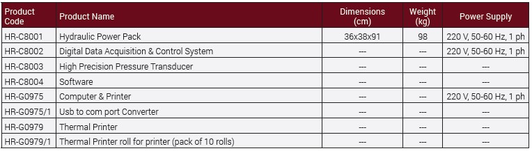
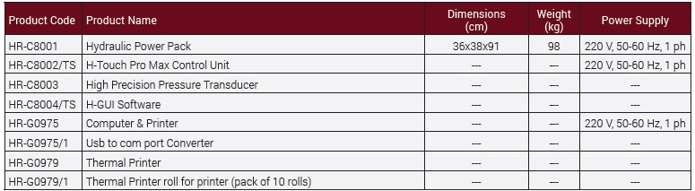
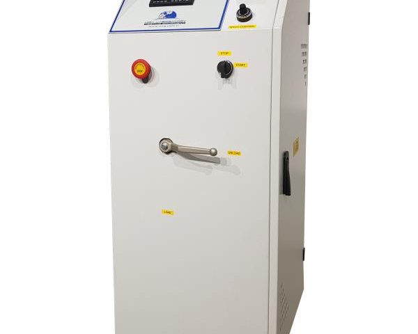
Hydraulic Power Pack

Automatic Hydraulic Power Pack, dual stage, controlled by digital readout unit is designed to supply the required oil to the load frames for loading.

Controller unit has a simple and compact configuration. The Hydraulic Power Pack, Control and Read out Units are positioned on the right hand side of the load frame for easier accessibility, increased productivity and for safer operations.

Very silent power pack can load the specimen between 1 kN/sec. to 20 kN/sec, with an accuracy of ±5%.  A Rapid approach pump is supplied as standard. Safety valve (maximum pressure valve) is used to avoid machine overloading.

Maximum working pressure of the system is 400 bar.

Dual Stage Pump

The dual stage pump is formed by two groups;

  1. Low pressure gear pump
  2. High pressure radial piston pump

On the dual stage pump, a high delivery, low pressure gear pump is used for rapid approach, while a low delivery, high pressure radial piston pump is used for test execution. The rapid approach facility shortens the time interval from piston start until the upper platen touches to the specimen. This excellent feature helps to save a lot of time when a large number of specimens are going to be tested.

Motor

The motor which drives the dual pumps in an AC motor and it is controlled by motor inverter. The variation in the oil flow is executed with the variation of the rotation speed of the motor.

Distribution Block

A distribution block is used to control the oil flow direction supplied by the dual stage pump, the following parts are fitted to the distribution block; Solenoid valve, Safety valve (max. pressure valve), Transducer, Low pressure gear pump and High pressure radial piston pump.

High Precision Pressure Transducer 

The range of Automatic Machines can be upgraded with option High Precision Pressure Transducer special calibration Class 1 starting from 1% of the full range.

This unique performance enables the machines to be used for a considerable number of applications including:

• Early age(2 or 3 days) compression strength tests
• Flexural and splitting tests by using proper accessories
• Mortar (Cement) compression tests by using proper accessories
• Core Testing

Oil Tank

The tank includes enough oil to fill the mechanism which pushes the ram during the test. The level and oil temperature can be seen on the indicator fitted to the tank. It has 25 L capacity. Hydraulic motor oil, number 46, must be used.

Digital Data Acquisition & Control System

The unit is designed to control the machine and processing of data from load-cells and pressure transducers which are fitted to the machine.

All the operations of the unit are controlled from the front panel consisting of a LCD display and function keys.

The unit has easy to use menu options.

Digital graphic display unit loading rate of the time of Testing and load values can be monitored.

Digital graphic display is able to draw real-time “Load vs. Time”.

Software

Sample, company, laboratory and test values can be entered in the programme.

Load-time graphic, test reports and sample reports can be taken.

Software provides test data, results, and the load-time graphs can be seen at LCD screen.

The Automatic Compression Machine can be controlled (Start, Stop commands) by a computer with the software free of charge. This software provides data acquisition and management for compression, tensile and splitting tensile test throughout the test execution. The advanced functions for data base management provide an easy navigation of all saved data. The test results certificate includes all descriptive information. Therefore, test parameters can be set and details about the test carried out such as client details, test type, specimen type, user info and other information required can be entered and printed out as well as test report and graph.

Software can be performed in Turkish and English.

Test results, graphics and properties of 24 different specimens can be saved in one folder. Old test folders can be reviewed.

User can highlight all 12 different specimen curves in different colors on the graphics.

Frequently used information like name and location of the laboratory, type and dimensions of mostly used specimens are held in memory and can be written automatically by right clicking on information boxes and selecting frequently used text in menu.

User can access any data of previously completed tests and use in his/ her new report since most of the tests have same structure and properties.

Main Features

  • Pace rate control from 1 kN/sec to 20 kN/sec depending on piston size.
  • Can control 2 frames (optional)
  • Can make test with load control.
  • Real time display of test graph.
  • Analog channels for different frame load cells
  • RS-232 serial port connecting for computer interface
  • LCD display
  • 2 different unit system selection; kN and kgf
  • Multi-language support (English and Turkish)
  • 2 different unit system selection; SI and Metric
  • Real-time clock and date
  • Free of charge PC software for the test control and printout the test report.

Safety Features

  • Maximum pressure valves to avoid machine overloading
  • Piston travel limit switch
  • Emergency stop button
  • Software controlled maximum load value
Semi-Automatic Flexural Testing Machine

The HİRA Semi-Automatic (Motorized) range of 100 kN, 200 kN, 300 kN and 400 kNcapacity Flexural Testing Machines have been designed for reliable and consistent testing of flexural test on standard concrete beams, concrete or natural stone kerbs, concrete paving flags, and natural stone slabs and tensile splitting test of concrete paving blocks with suitable apparatus.

The Semi-Automatic Flexural Testing Machines consist of;

Heavy Duty Welded Load Frame,
Semi-Automatic Hydraulic Power Pack,
Digital Readout Unit
Flexural test assemblies should be ordered separately.

Flexural Load Frame

The multipurpose HİRA Flexural Testing Frames are designed for minimum deflection at maximum load resulting in very high accuracy. The load frame is a welded steel fabrication carrying the ram fitted to the steel base. All Frames have a single acting up stroking ram with over travel switch protection to stop the machine when maximum ram travel is reached. A load cell is used for load measurements on all frames.

Flexural Frames are designed to accept all accessories required for flexural or compression tests.

Flexural Frames are 100 kN, 200 kN, 300 kN capacity U Type and 300 kN, 400 kN capacity C Type open structure designed to allow easy and practical front loading of the specimen.

The very rigid C type design is ideal either for conventional flexural test or for more sophisticated tests such as deformability and ductility index.

The load frame provides the stability needed for accurate and repeatable test results over the years of operation.

All frames can be connected to HİRA compression machine as a second frame or can be used with any HİRA power pack as an independent Flexural Machine.

The main characteristics are:

• High stability welded assembly
• High accuracy load measurement with load cells
• Can accept wide range of accessories for mentioned standards
• Can be connected to HİRA Compression Machine or Hydraulic Power Pack

Flexural Testing Accessories

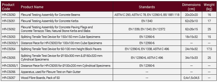
Flexural Testing Assembly for Concrete Beams 

The test assembly is used for 3 or 4 point flexural tests on 100 or 150 mm Concrete Beams.
The set consist of 2 upper and 2 lower rollers of Ø38 x 160 mm.
The distance of lower bearers can be adjusted between 100mm and 800mm. The distance between upper bearers can be set to 100 mm or 150 mm.
For 3 point testing one of the bearers can be removed and the other placed in the center.

Flexural Testing Assembly for Concrete Kerbs 

The test assembly is used for flexural tests on Concrete Kerbs.
The set consists of 2 lower rollers of Ø 20 x 620mm and Ø 40 mm upper loading piston with ball seating assembly.
The distance of lower rollers can be adjusted between 100 mm to 800 mm.

Flexural Test Assembly for Concrete Paving Flags and Concrete Terrazzo Tiles, Natural Stone Kerbs and Slabs

The test assembly is used for flexural tests on Concrete Paving Flags and Concrete Terrazzo Tiles, Natural Stone Kerbs and Slabs.
The set consists of 2 lower rollers and upper roller of Ø 20x 620 mm.
The distance of lower rollers can be adjusted between 100 mm to 800 mm.

Splitting Tensile Test Device for Block Pavers

Splitting Tensile Test Device for Block Pavers is accessory for compression machines for measuring the splitting tensile strengths of 60-100 mm height x 220 mm length concrete block pavers according to the requirements of the related standards.

Splitting Tensile Test Device for Concrete Cubes

Splitting Tensile Test Device for Concrete Cubes is accessory for compression machines for measuring the splitting tensile strengths of 150 mm cube concrete specimens according to the requirements of the related standards.

Distance Piece for Splitting Tensile Test Device for Concrete Cubes

Can be used for 100 mm cube concrete specimens by using this Distance pieces with Splitting Tensile Test Device for Concrete Cubes.

Splitting Tensile Test Device for Cylinders

Splitting Tensile Test Device for Cylinders is accessory for compression machines for measuring the splitting tensile strengths of Ø150×300 mm and Ø160×320 mm cylindrical specimens according to the requirements of the related standards.

Distance Piece for Splitting Tensile Test Device for Cylinders

Can be used for Ø100×200 mm Cylindrical Specimens by using this Distance pieces with Splitting Tensile Test Device for Concrete Cylinders.

SEMI-AUTOMATIC (MOTORIZED) HYDRAULIC POWER PACK AND DIGITAL READOUT UNIT 

Semi-Automatic (Motorized) Hydraulic Power Pack

The Semi-Automatic (Motorized) Power Pack, controlled by a pressure rate control valve is designed to supply the required oil to the load frames for loading. The power pack can load different frames with required pace rates. A pump is supplied as standard. The power pack is equipped with a safety valve (maximum pressure valve) to avoid machine overloading. Maximum working pressure of the system is 400bar.

Single Stage Pump

The single stage pump is formed by;
High pressure pump
On the single stage pump, high pressure pump is used for test execution.

Motor

The motor which drives the pump in an AC motor.

Distribution Block
A distribution block is used to control the oil flow direction supplied by single stage pump. Loading and unloading process and pace rate adjustment is done from the arms on the distribution block. The following parts are fitted to the distribution block; Solenoid valve, Safety valve (max. pressure valve), Load Cell and High pressure radial piston pump.
High Precision Pressure Transducer 

The HİRA range of Semi-Automatic Machines can be upgraded with option High Precision Pressure Transducer special calibration Class 1 starting from 1% of the full range.

This unique performance enables the machines to be used for a considerable number of applications including:

• Early age(2 or 3 days) compression strength tests
• Flexural and splitting tests by using proper accessories
• Mortar (Cement) compression tests by using proper accessories
• Core Testing

Oil Tank

The tank includes enough oil to fill the mechanism which pushes the ram during the test. The level and oil temperature can be seen on the indicator fitted to the tank. It has 15 L capacity. Hydraulic motor oil, number 46, must be used.

Digital Readout Unit 

The Digital Readout Unit has been designed to use with load cells or pressure transducers on different material test applications.

The peak value and the load change during the test are displayed on the screen.

• Peak value hold property
• Easypreloadzeroing
• 600 KHz High SpeedInputFrequency
• 6 Digits

Safety Features

• Maximum pressure valves to avoid machine overloading
• Piston travel limit switch
• Emergency stop button

Hydraulic Power Pack And Digital Data Acquisition & Control System

Hydraulic Power Pack

Automatic Hydraulic Power Pack, dual stage, controlled by digital readout unit is designed to supply the required oil to the load frames for loading.

Controller unit has a simple and compact configuration.

Very silent power pack can load the specimen between 1 kN/sec. to 20 kN/sec, with an accuracy of ±5%.  A Rapid approach pump is supplied as standard. Safety valve (maximum pressure valve) is used to avoid machine overloading.

Maximum working pressure of the system is 400 bar.

Dual Stage Pump

The dual stage pump is formed by two groups;

  1. Low pressure gear pump
  2. High pressure radial piston pump

On the dual stage pump, a high delivery, low pressure gear pump is used for rapid approach, while a low delivery, high pressure radial piston pump is used for test execution. The rapid approach facility shortens the time interval from piston start until the upper platen touches to the specimen. This excellent feature helps to save a lot of time when a large number of specimens are going to be tested.

Motor

The motor which drives the dual pumps in an AC motor and it is controlled by motor inverter. The variation in the oil flow is executed with the variation of the rotation speed of the motor.

Distribution Block

A distribution block is used to control the oil flow direction supplied by the dual stage pump, the following parts are fitted to the distribution block; Solenoid valve, Safety valve (max. pressure valve), Transducer, Low pressure gear pump and High pressure radial piston pump.

High Precision Pressure Transducer 

The  range of Automatic Machines can be upgraded with option High Precision Pressure Transducer special calibration Class 1 starting from 1% of the full range.

This unique performance enables the machines to be used for a considerable number of applications including:

• Early age (2 or 3 days) compression strength tests
• Flexural and splitting tests by using proper accessories
• Mortar (Cement) compression tests by using proper accessories
• Core Testing

Oil Tank

The tank includes enough oil to fill the mechanism which pushes the ram during the test. The level and oil temperature can be seen on the indicator fitted to the tank. It has 25 L capacity. Hydraulic motor oil, number 46, must be used.

Digital Data Acquisition & Control System

The unit is designed to control the machine and processing of data from load-cells and pressure transducers which are fitted to the machine.

All the operations of the unit is controlled from the front panel consisting of a LCD display and function keys.

The unit has easy to use menu options.

Digital graphic display unit loading rate of the time of Testing and load values can be monitored.

Digital graphic display is able to draw real-time “Load vs. Time”.

Software

Sample, company, laboratory and test values can be entered in the programme.

Load-time graphic, test reports and sample reports can be taken.

Software provides test data, results, and the load-time graphs can be seen at LCD screen.

The Automatic Compression machine can be controlled (Start, Stop commands) by a computer with the software free of charge. This software provides data acquisition and management for compression, tensile and splitting tensile test throughout the test execution. The advanced functions for data base management provide an easy navigation of all saved data. The test results certificate includes all descriptive information. Therefore, test parameters can be set and details about the test carried out such as client details, test type, specimen type, user info and other information required can be entered and printed out as well as test report and graph.

Software can be performed in Turkish and English.

Test results, graphics and properties of 24 different specimens can be saved in one folder. Old test folders can be reviewed.

User can highlight all 12 different specimen curves in different colors on the graphics.

Frequently used information like name and location of the laboratory, type and dimensions of mostly used specimens are held in memory and can be written automatically by right clicking on information boxes and selecting frequently used text in menu.

User can access any data of previously completed tests and use in his/ her new report since most of the tests have same structure and properties.

Main Features

  • Pace rate control from 1 kN/sec to 20 kN/sec depending on piston size.
  • Can control 2 frames (optional)
  • Can make test with load control.
  • Real time display of test graph.
  • Analog channels for different frame load cells
  • RS-232 serial port connecting for computer interface
  • LCD display
  • 2 different unit system selection; kN and kgf
  • Multi-language support (English and Turkish)
  • 2 different unit system selection; SI and Metric
  • Real-time clock and date
  • Free of charge PC software for the test control and printout the test report.

Hydraulic Power Pack And H-TOUCH PRO MAX Control Unit

Hydraulic Power Pack

Automatic Hydraulic Power Pack, dual stage, controlled by H-Touch Pro Max Control Unit is designed to supply the required oil to the load frames for loading.

Controller unit has a simple and compact configuration. The Hydraulic Power Pack, Control and Read out Units are positioned on the right-hand side of the load frame for easier accessibility, increased productivity and for safer operations.

Very silent power pack can load the specimen between 1 kN/sec. to 20 kN/sec, with an accuracy of ±5%.  A Rapid approach pump is supplied as standard. Safety valve (maximum pressure valve) is used to avoid machine overloading.

Maximum working pressure of the system is 400 bar.

Dual Stage Pump

The dual stage pump is formed by two groups;

  1. Low pressure gear pump

    2. High pressurera dial piston pump

On the dual stage pump, a high delivery, low pressure gear pump is used for rapid approach, while a low delivery, high pressure radial piston pump is used for test execution. The rapid approach facility shortens the time interval from piston start until the upper platen touches to the specimen. This excellent feature helps to save a lot of time when a large number of specimens are going to be tested.

Motor

The motor which drives the dual pumps in an AC motor and it is controlled by motor inverter. The variation in the oil flow is executed with the variation of the rotation speed of the motor.

Distribution Block

A distribution block is used to control the oil flow direction supplied by the dual stage pump, the following parts are fitted to the distribution block; Solenoid valve, Safety valve (max. pressure valve), Transducer, Low pressure gear pump and High pressure radial piston pump.

High Precision Pressure Transducer 

The range of Automatic Machines can be upgraded with option High Precision Pressure Transducer special calibration Class 1 starting from 1% of the full range.

This unique performance enables the machines to be used for a considerable number of applications including:

  • Early age(2 or 3 days) compression strength tests
  • Flexural and splitting tests by using proper accessories
  • Mortar (Cement) compression tests by using proper accessories
  • Core Testing

Oil Tank

The tank includes enough oil to fill the mechanism which pushes the ram during the test. The level and oil temperature can be seen on the indicator fitted to the tank. It has 25 L capacity. Hydraulic motor oil, number 46, must be used.

Digital Data Acquisition & Control System

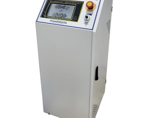
TEST H-Touch Pro Max Control Unit is designed to control the automatic compressive, flexural and splitting tensile strength tests of construction materials such as concrete, cement mortar, masonry units, paving blocks, roofing tiles by processing of data from load-cells, pressure transducers or displacement transducers which are fitted to the machine.

All the operations of H-Touch Pro Max Control Unit are controlled from the front panel color resistive of TFT-LCD Touchscreen display and function keys.

The unit has easy to use menu options.

It displays all menu option listings simultaneously, allowing the operator to access the required option in a seamless manner to activate the option or enter a numeric value to set the test parameters.

H-Touch PRO Max Control Unit enable simultaneously display machine status, test values, warnings during operation and test graphs such as load-time or load-displacement curves in real time.

Digital graphic display of the unit is able to draw real-time “Load vs. Time” or “Stress vs. Time” graphics.

Main Features of H-Touch Pro Max Control Unit

  • 2 analog channels for load cell or pressure sensors or displacement sensors.
  • Can control 2 frames
  • Provides load control of two separate testing frames with Closed-loop PID.
  • Optionally supplied-integrated thermal printer (If requested, must be specified in the order)
  • Real-time numeric display of load, loading rate and load/ time curves with automatic resolution adjustment on the touchscreen
  • Up to 8-point calibration support and adjustable digital gains for every channel
  • User-customizable load, position limits and test termination conditions
  • Backup and recall option for device settings
  • Recalling to factory default settings option.
  • Easy recall of embedded test parameters for different types of tests and sample sizes
  • Storage capacity up to 10.000 test result or 80 hours real time data recording with 1 sample per second recording interval (recording interval is variable).
  • Graph axes on touchscreen can be configured for different tests and configurations
  • The axes of the graph drawn on the device can be set to constant maximum values ​​or axes can be automatically scaled according to the data
  • Three different unit system selection; kN- Mpa -mm or lbf- psi- in or kgf- kgf/cm²- cm
  • Real time and adjustable date/time.
  • Multi-language support (English, French, Spanish, Turkish, Russian…)
  • LAN connection for instantaneous transfer of test data to PC.
  • USB port support for transfer of test data to a flash drive.
  • Password Protection for machine settings, calibration and channel menus
  • Record of test results in txt and MS excel format on pre-defined intervals
  • 5 different visual themes
  • Customizable IP

Hardware

  • 2 fully customizable analog channels with 24-bit ADC and PGA-FPGA circuit
  • 800×480 pixel and 65535 color resolution TFT-LCD touchscreen
  • 33 Hz control loop
  • 32 Bit, 120 MHz ARM CORTEX M3 micro-PROcessor (CPU) for data acquisition
  • 32 Bit, 400 MHz ARM CORTEX M3 micro-PROcessor (CPU) for data display
  • Additional memory support up to 32 GB via external USB flash drive
  • Support for -optionally supplied- integrated thermal printer
  • Real time display of test graph
  • LAN connection for instantaneous transfer of test data to PC.
  • USB port support for transfer of test data to a flash drive

Software

TEST H-GUI Software has been designed for data acquisition, processing controlling, presentation and reporting compressive, flexural and splitting tensile strength tests of construction materials such as concrete, cement mortar, masonry units, paving blocks, roofing tiles with appropriate Automatic Compression/Flexure Testing Machines and also with a computer.

The Automatic Compression Machine can be controlled (Start, Stop commands) by a computer with the TEST H-GUI Software free of charge.

The advanced functions for database management provide an easy navigation of all saved data.

Test parameters can be set and details about the test carried out such as Test Type, Sample Type, Report details, Customer details, Sample details and other information required can be entered in the software.

This informations and “Load vs. Time” or “Stress vs. Time” graphics can be seen and printed out on the Test Report.

Following tests can be done with the TEST H-GUI Software;

  • Compressive Strength of Concrete Cylinders / Cubes
  • Flexural Strength of Concrete Beams
  • Compressive Strength of Cement Mortars
  • Flexural Strength of Cement Mortars
  • Tensile Splitting Strength of Concrete Paving Blocks
  • Tensile Splitting Strength of Concrete Cylinders / Cubes
  • Flexural Strength of Roofing Tiles
  • Flexural Strength of Concrete Kerbs
  • Compressive Strength of Masonry Units

Main Features of H-GUI Software

  • Multi-language support and customizable user interface
  • 30 Tests Results, Graphics and Properties Storage Capacity in One Test File
  • Exporting test results to database
  • Advanced test graphical interface
  • Option to store and recall test information
  • Modification of test machine parameters using the software
  • Able to save frequently used texts in memory and recall them when necessary
  • Exporting reports and graphs
  • Flexible report and graph formats
  • Help and user manual display

Semi Automatic Motorized Hydraulic Power Pack And Digital Readout Unit

Semi-Automatic (Motorized) Hydraulic Power Pack

The Semi-Automatic (Motorized) Power Pack, controlled by a pressure rate control valve is designed to supply the required oil to the load frames for loading. The power pack can load different frames with required pace rates. A pump is supplied as standard. The power pack is equipped with a safety valve (maximum pressure valve) to avoid machine overloading. Maximum working pressure of the system is 400 bar.

Dual Stage Pump

The dual stage pump is formed by two groups;

  1. Low pressure gear pump
  2. High pressure radial piston pump

On the dual stage pump, a high delivery, low pressure gear pump is used for rapid approach, while a low delivery, high pressure radial piston pump is used for test execution. The rapid approach facility shortens the time interval from piston start until the upper platen touches to the specimen. This excellent feature helps to save a lot of time when a large number of specimens are going to be tested.

Motor

The motor which drives the pump in an AC motor.

Distribution Block

A distribution block is used to control the oil flow direction supplied by the pump. Loading and unloading process and pace rate adjustment is done from the arms on the distribution block. The following parts are fitted to the distribution block; Safety valve (max. pressure valve) and Transducer.

High Precision Pressure Transducer 

The range of Semi-Automatic Machines can be upgraded with option High Precision Pressure Transducer special calibration Class 1 starting from 1% of the full range.

This unique performance enables the machines to be used for a considerable number of applications including:

• Early age(2 or 3 days) compression strength tests
• Flexural and splitting tests by using proper accessories
• Mortar (Cement) compression tests by using proper accessories
• Core Testing

Oil Tank

The tank includes enough oil to fill the mechanism which pushes the ram during the test. The level and oil temperature can be seen on the indicator fitted to the tank. It has 15 L capacity. Hydraulic motor oil, number 46, must be used.

Digital Readout Unit 

The Digital Readout Unit has been designed to use with load cells or pressure transducers on different material test applications.

The peak value and the load change during the test are displayed on the screen.

• Peak hold property
• Easy preload zeroing
• 5 Digits
• Multi-point Calibration

LPI Digital Readout Unit 

LPI Digital Readout Unit is used  for reading of the applied load on load cells or pressure transducers in different material test applications.

  • Can operate with 2 x AA batteries or 5V AC adapter
  • Real time numeric display of load and load pressure
  • 1 channel with two different calibration table (by changing the sensor belong to other frame, the unit can be control for second test frame)
  • Peak hold property
  • Multi-point calibration
  • Easy preload zeroing
  • 8 keys keyboard
  • RS232  Serial port for PC or thermal or dot matrix printer

Concrete Pipe Testing Machine (Peak Load)

1000 kN capacity Concrete Pipe Testing Machines are designed for the Peak Load Tests on Sewer and Drain Pipes, Concrete Pipes, Fittings, Cones on from 200 mm up to 3700 mm (outer diameters) pipes. Can be used for concrete pipes with a length up to 3000 mm.

600 kN capacity Concrete Pipe Testing Machines are designed for the Peak Load Tests on Sewer and Drain Pipes, Concrete Pipes, Fittings, Cones on from 200 mm up to 2000 mm (outer diameters) pipes. Can be used for concrete pipes with a length up to 2000 mm.

Please contact with us for different dimensions and capacity of Concrete Pipe Testing Machines.

Concrete Pipe Testing Machines consist of;

• Load Frame
• Automatic Hydraulic Power Pack and
• Digital data acquisition & control system

Concrete Pipe Testing Load Frame

The frames are rigid 2 column constructions with superior axial and lateral stiffness and are precision aligned. The load-controlled double acting piston is integrated to upper beam. The actuator has anti-rotation system to prevent the natural tendency of the actuator to rotate. The stroke of the double acting actuator is 300 mm. Load cell is used for precise load measurement and closed loop control.

The rectangular shaped top bearer is detachable from the actuator and the bottom bearer is V-shaped with an angle of 150°. During pipe loading the system doesn’t permit top bearer to move at horizontal plane and allows it to move at vertical plane of a minimum value of ±8°. Upper crosshead height adjustment is done with electric motor drive for easy and precise test set up and manual through locking pins are used to fix the upper crosshead.

There are 2 options depending on frame fixing system, with or without chassis.First option is not including carrying chassis for the machine. These types of frames have to be anchored to concrete base. Steel fasteners and anchorage plan are sent to the customer before installation. Steel fasteners have to be anchored to concrete base by customer according to plan. Following this anchorage process, the frame is assembled.Second option is including metal carrying chassis for the machine.

HYDRAULIC POWER PACK AND DIGITAL DATA ACQUISITION & CONTROL SYSTEM

HydraulicPower Pack

Automatic Hydraulic Power Pack, dual stage, controlled by digital readout unit is designed to supply the required oil to the load frames for loading.
Controller unit has a simple and compact configuration.

Very silent power pack can load the specimen between 1 kN/sec. to 20 kN/sec, with an accuracy of ±5%.
A Rapid approach pump is supplied as standard. Safety valve (maximum pressure valve) is used to avoid machine overloading.
Maximum working pressure of the system is 410 bar.

Dual Stage Pump

The dual stage pump is formed by two groups;
1. Low pressure gear pump
2. High pressure radial piston pump

On the dual stage pump, a high delivery, low pressure gear pump is used for rapid approach, while a low delivery, high pressure radial piston pump is used for test execution. The rapid approach facility shortens the time interval from piston start until the upper platen touches to the specimen. This excellent feature helps to save a lot of time when a large number of specimens are going to be tested.

Digital Data Acquisition& Control System

The unit is designed to control the machine and processing of data from load-cells and pressure transducers which are fitted to th machine.

All the operations of the unit is controlled from the front panel consisting of a LCD display and function keys.

The unit has easy to use menu options.

Digital graphic display unit loading rate of the time of Testing and load values can be monitored.

Digital graphic display is able to draw real-time “Load vs. Time”.

Software

The Concrete Pipe Testing Software is supplied free of charge with the Concrete Pipe Testing Machine.

Sample, company, laboratory and test values can be entered in the programme.

Load-time graphic, test reports and sample reports can be taken.

Software provides test data, results, and the load-time graphs can be seen at LCD screen.

The Concrete Pipe Testing Machine can be controlled (Start, Stop commands) by a computer with the software free of charge.

This software provides data acquisition and management for compression tests throughout the test execution.

The advanced functions for data base management provide an easy navigation of all saved data. The test results certificate includes all descriptive information.

Therefore, test parameters can be set and details about the test carried out such as client details, test type, specimen type, user info and other information required can be entered and printed out as well as test report and graph.

Software can be performed in Turkish and English.

Frequently used information like name and location of the laboratory, type and dimensions of mostly used specimens are held in memory and can be written automatically by right clicking on information boxes and selecting frequently used text in menu.

User can access any data of previously completed tests and use in his/ her new report since most of the tests have same structure and properties.

Main Features

• Pace rate control from 1 kN/sec to 20 kN/sec depending on piston size.
• Can control 2 frames (optional)
• Can make test with load control.
• Real time display of test graph.
• Analog channels for different frame load cells
• RS-232 serial port connecting for computer interface
• LCD display
• 2 different unit system selection; kN and kgf
• Multi-language support (English and Turkish)
• 2 different unit system selection; SI and Metric
• Real-time clock and date
• Free of charge PC software for the test control and printout the test report.

Safety Features

• Maximum pressure valves to avoid machine overloading
• Piston travel limit switch

• Emergency stop button
• Software controlled maximum load value
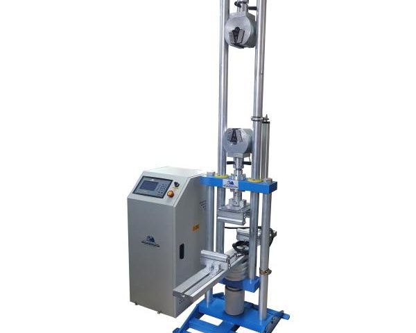
Electromechanical Flexural-Compression Testing Machine

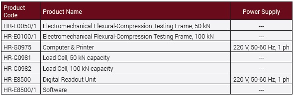
Electromechanical Flexural-Compression Testing Machine can perform Flexural-Compression Tests of various types of materials.

It is produced with a capacity of 50 kN or 100 kN.

The device works with an Electromechanical Motor.

Piston movement is limited by 2 switches located at the top and bottom of the piston.

The Electromechanical Flexural-Compression Testing Machine machine consists of;

  • Load Frame
  • 50 kN or 100 kN Load Cell according to device capacity,
  • Movable Upper Plate for compression tests,
  • Digital graphic readout unit
  • Software

Accessories should be ordered separately according to the type of test to be performed for flexure tests.

Load Frame
The Load Frame consist of 2 rigid columns, a cast iron base with gear box inside and a steel bridge to hold the Load cell and accessories.
The vertical distance can be adjusted by the help of the upper platen.
The distance between the columns can be adjusted up to 1 meter.

Digital Graphic Readout Unit
The device can be controlled from the computer automatically or run from the control unit automatically or manually.
Load/stress values can be read from the computer or LCD screen Graphic Readout Unit.
The Load vs Time graph can be seen from the LCD screen during the test.
Test data can be stored by the computer after failure.
The pace rate can be adjusted between 0,05 and 24 kN/sn.

Software
The device can be connected to any computer with Ethernet cable.
Thanks to software, different types of user and sample data can be stored and printed out the test report.
Compression-Flexural Software is provided free of charge with the device.

FLEXURAL TESTING ACCESSORIES

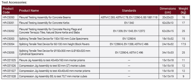
Flexural Testing Assembly for Concrete Beams 

The test assembly is used for 3 or 4 point flexural tests on 100 or 150 mm Concrete Beams.

The set consist of 2 upper and 2 lower rollers of Ø38 x 160 mm.

The distance of lower bearers can be adjusted between 100 mm and 800 mm. The distance between upper bearers can be set to 100 mm or 150 mm.

For 3 point testing one of the bearers can be removed and the other placed in the center.

Flexural Testing Assembly for Concrete Kerbs 

The test assembly is used for flexural tests on Concrete Kerbs.

The set consists of 2 lower rollers of Ø 20 x 620 mm and Ø 40 mm upper loading piston with ball seating assembly.

The distance of lower rollers can be adjusted between 100 mm to 800 mm.

Flexural Test Assembly for Concrete Paving Flags and Concrete Terrazzo Tiles, Natural Stone Kerbs and Slabs

The test assembly is used for flexural tests on Concrete Paving Flags and Concrete Terrazzo Tiles, Natural Stone Kerbs and Slabs.

The set consists of 2 lower rollers and upper roller of Ø 20x 620 mm.

The distance of lower rollers can be adjusted between 100 mm to 800 mm.

Splitting Tensile Test Device for Block Pavers
Splitting Tensile Test Device for Block Pavers is accessory for compression machines for measuring the splitting tensile strengths of 60-100 mm height x 220 mm length concrete block pavers according to the requirements of the related standards.

Splitting Tensile Test Device for Concrete Cubes
Splitting Tensile Test Device for Concrete Cubes is accessory for compression machines for measuring the splitting tensile strengths of 150 mm cube concrete specimens according to the requirements of the related standards.

Splitting Tensile Test Device for Cylinders
Splitting Tensile Test Device for Cylinders is accessory for compression machines for measuring the splitting tensile strengths of Ø150×300 mm and Ø160×320 mm cylindrical specimens according to the requirements of the related standards.

CEMENT COMPRESSION & FLEXURAL TEST ACCESSORIES

Cement Flexural Jig Assembly ( 40x40x160 mm)
It is used for flexural strength test of 40x40x160 mm cement samples.

Cement Compression Jig Assembly (40x40x40 mm)
It is used for compressive strength test of 40x40x160 mm cement samples.

Cement Compression Jig Assembly (50x50x50 mm)
It is used for compressive strength test of 50x50x50 mm cement samples.

Cement Compression Jig Assembly (70,7 mm)
It is used for compressive strength test of 70,7 mm cement samples.

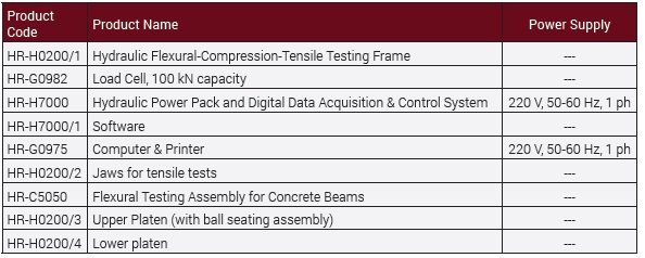
Hydraulic Flexural-Compression-Tensile Testing Machine

Hydraulic Flexural-Compression-Tensile Testing Machine is used in 3-point and 4-point Flexural Tests, Compression and Tensile tests of different construction materials.

It is produced with a capacity of 100 kN.

With the help of the jaws on the upper part of the device, it allows Tensile tests of cylinder and flat materials with diameters between 0-8 mm.

3-point and 4-point Flexural Tests can be performed by using the Flexural Testing Assembly for Concrete Beams at the bottom of the device.

Compression tests also can be performed by using the Upper Platen (with ball seating assembly) and Lower platen.

The speed range can be adjusted manually or automatically.

Supplied with Automatic Hydraulic Power Pack and Digital Data Acquisition & Control System.

A displacement sensor is used to measure the elongation in tensile tests.

Load Cell is used for load measurements in flexural and compression tests.

Flexural-Compression-Tensile Software is provided free of charge with the device.

Flexural Testing Assembly for Concrete Beams should be ordered separately.

Upper Platen (with ball seating assembly) and Lower platen should be ordered separately.